 to supply AC/DC radio's (like the American AA5 or European Uutjes)
from 230V AC.
It involves placing the A supply (heater chain) and B supply (plate voltage)
in series, combined with a ballast capacitor.
Because I first saw this solution in the
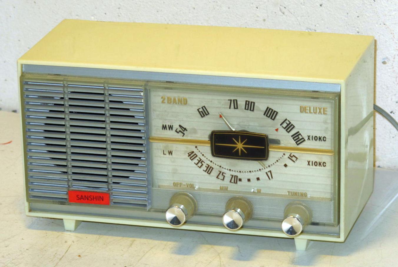
Sanshin KR55,
I usually refer to it as the "Sanshin Supply".
to supply AC/DC radio's (like the American AA5 or European Uutjes)
from 230V AC.
It involves placing the A supply (heater chain) and B supply (plate voltage)
in series, combined with a ballast capacitor.
Because I first saw this solution in the
Sanshin KR55,
I usually refer to it as the "Sanshin Supply".
In a transformerless power supply, as used in ACDC radios,
 this isn't possible and both the A and B supply
are derived directly from the mains.
For the A supply, the heaters are connected in series
(so the radio must use tubes with equal heater current),
and, together with dial lights,
require a voltage of about 110 to 120V.
For the B supply,
the mains voltage is fed through a rectifier
to the filter capacitors,
so the B+ voltage will be very dependent on the mains voltage.
this isn't possible and both the A and B supply
are derived directly from the mains.
For the A supply, the heaters are connected in series
(so the radio must use tubes with equal heater current),
and, together with dial lights,
require a voltage of about 110 to 120V.
For the B supply,
the mains voltage is fed through a rectifier
to the filter capacitors,
so the B+ voltage will be very dependent on the mains voltage.
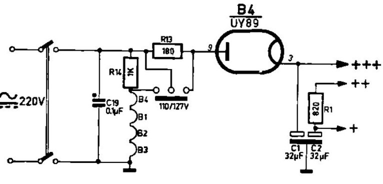
The picture to the left shows the power supply of the Philips B0X19U. In 110V operation, R13 and R14 are shorted. To enable 220V operation, the power selector is released, placing R14 and R13 in series. The purpose of R14, referred to as a ballast resistor, is to reduce the current through the heaters. The purpose of R13, referred to as a limiter, is to limit current peaks through the rectifier.
 Understandibly, the power consumption is much higher
on 220V than on 110V.
Not only because of the power in R13 and R14,
but also because of the much higher plate supply.
The service manual lists the consumption
as 17W on 110V and 43W on 220V,
which is confirmed by my own measurements
and by InfraRed pictures of radios.
Understandibly, the power consumption is much higher
on 220V than on 110V.
Not only because of the power in R13 and R14,
but also because of the much higher plate supply.
The service manual lists the consumption
as 17W on 110V and 43W on 220V,
which is confirmed by my own measurements
and by InfraRed pictures of radios.
Power consumption is a problem because power generates heat,
and accelerates the detoriation of radio components.
It is possible to use a capacitor instead of R14,
to avoid the heat generated in the ballast resistor.
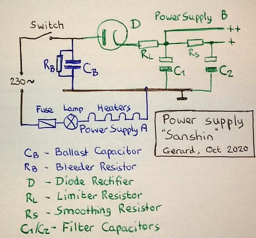 by placing the A and B supplies in series with each other.
The A supply is then bypassed with a ballast capacitor.
Of course, this idea can be found in many variations,
so different implementations may differ in details,
but this diagram gives the general idea.
by placing the A and B supplies in series with each other.
The A supply is then bypassed with a ballast capacitor.
Of course, this idea can be found in many variations,
so different implementations may differ in details,
but this diagram gives the general idea.
The blue lines give the A supply: the mains current runs through the heaters (and possibly dial lamps) and through the ballast capacitor CB. Observe that circuit ground is the connection between the heaters and CB! The green lines give the B supply; AC over CB is rectified to serve as B+. The AC over CB may be as high as 200V, but the resistance of the heaters serve as both ballast and limiter, and the voltage on C1 can be around 100 to 120V.
It is common that one side of the heater chain is grounded, usually the heater of the AF pre-amp is grounded. The plate of the output tube is most often supplied from C1 (indicated as ++), while its screen and the other tubes are supplied from C2 (indicated +).
The first generation of consumer radios,
often home built by their users,
were supplied with three battaries.
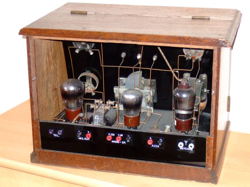 The A battery spplied the heaters,
and this was most often a wet rechargeable battery (4V accu).
The B battery was a high voltage pile
feeding the plates (90V dry pile).
Finally, a C battery would give
the negative bias for the output tube.
Its tension would be 9 to 15V,
and it gives zero current,
so the C battery could last for 10 to 20 years
(until it died of aging).
Since the nineteen thirties, grid biassing is either
done by a cathode resistor (automatic biassing),
or the C tension is derived from a resistor
in the negative side of the B supply.
The A battery spplied the heaters,
and this was most often a wet rechargeable battery (4V accu).
The B battery was a high voltage pile
feeding the plates (90V dry pile).
Finally, a C battery would give
the negative bias for the output tube.
Its tension would be 9 to 15V,
and it gives zero current,
so the C battery could last for 10 to 20 years
(until it died of aging).
Since the nineteen thirties, grid biassing is either
done by a cathode resistor (automatic biassing),
or the C tension is derived from a resistor
in the negative side of the B supply.
In the schema you find a Bleeder Resistor RB in parallel to the ballast CB, and it is there to prevent non-lethal but very unpleasant electrical shocks. If the mains plug is pulled from the wall socket while playing, CB may be charged to up to 300V, a voltage which may be present on the plug pins for minutes. Of course, there is no danger of this shock when the set is neatly switched off before unplugging. The value of RB isn't very critical, I usually try to have the product CBxRB around 0.5s.
You can add a fuse to protect the tube heaters from a short in CB.
A dial lamp can be connected in series with the heaters and they will not burn out when switching the set on. In the original situation, the startup current is very high (because cold heaters have low resistance) and will destroy the light bulbs. The ballast capacitor does not allow high startup currents.
 The Sanshin modification does not make
your radio any safer!
The circuit ground is not connected to one of the mains wires,
but this does not mean it is safe to touch it.
Ground is connected to one of the mains wires by CB
and to the other via the heater chain,
and both pass enough current to kill you.
So, touching the circuitry is as dangerous
as touching the original AA5 or Uutje circuitry.
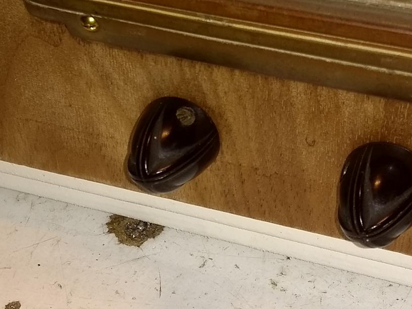
Unfortunately, some American 110V radios are very touch-unsafe.
The photo shows the knobs of the Weston,
with screws just 0.8mm onder the surface and hot on the mains!
The Sanshin modification does not make
your radio any safer!
The circuit ground is not connected to one of the mains wires,
but this does not mean it is safe to touch it.
Ground is connected to one of the mains wires by CB
and to the other via the heater chain,
and both pass enough current to kill you.
So, touching the circuitry is as dangerous
as touching the original AA5 or Uutje circuitry.
Unfortunately, some American 110V radios are very touch-unsafe.
The photo shows the knobs of the Weston,
with screws just 0.8mm onder the surface and hot on the mains!
The value of the ballast capacitor can be computed with CapCalc.
| Ih (mA) |
CB (µF) |
Example |
|---|---|---|
| 100 | 1.5 | Novak 491 |
| 150 | 2.2 | Teletone 111 |
| 200 | 3.0 | |
| 300 | 4.4 | Weston |
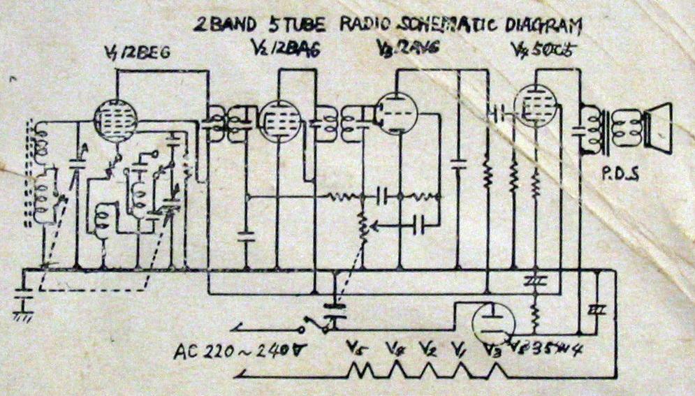 Sanshin KR55,
of which the schema is on the right.
It has a single pole power switch and a 200mA fuse
(not on schema).
The heater current is 150mA, because the common AA5 tubes are used.
There is no dial light.
The original ballast capacitor was a 2µF paper capacitor,
which had increased to 2.5µF over time.
The radio functioned fine with this higher value,
which taught me that the exact ballast value isn't very critical.
(Though, with more current through the heaters,
power consumption will increase,
not only because of the extra power in the heaters,
but also by higher B current.)
Sanshin KR55,
of which the schema is on the right.
It has a single pole power switch and a 200mA fuse
(not on schema).
The heater current is 150mA, because the common AA5 tubes are used.
There is no dial light.
The original ballast capacitor was a 2µF paper capacitor,
which had increased to 2.5µF over time.
The radio functioned fine with this higher value,
which taught me that the exact ballast value isn't very critical.
(Though, with more current through the heaters,
power consumption will increase,
not only because of the extra power in the heaters,
but also by higher B current.)
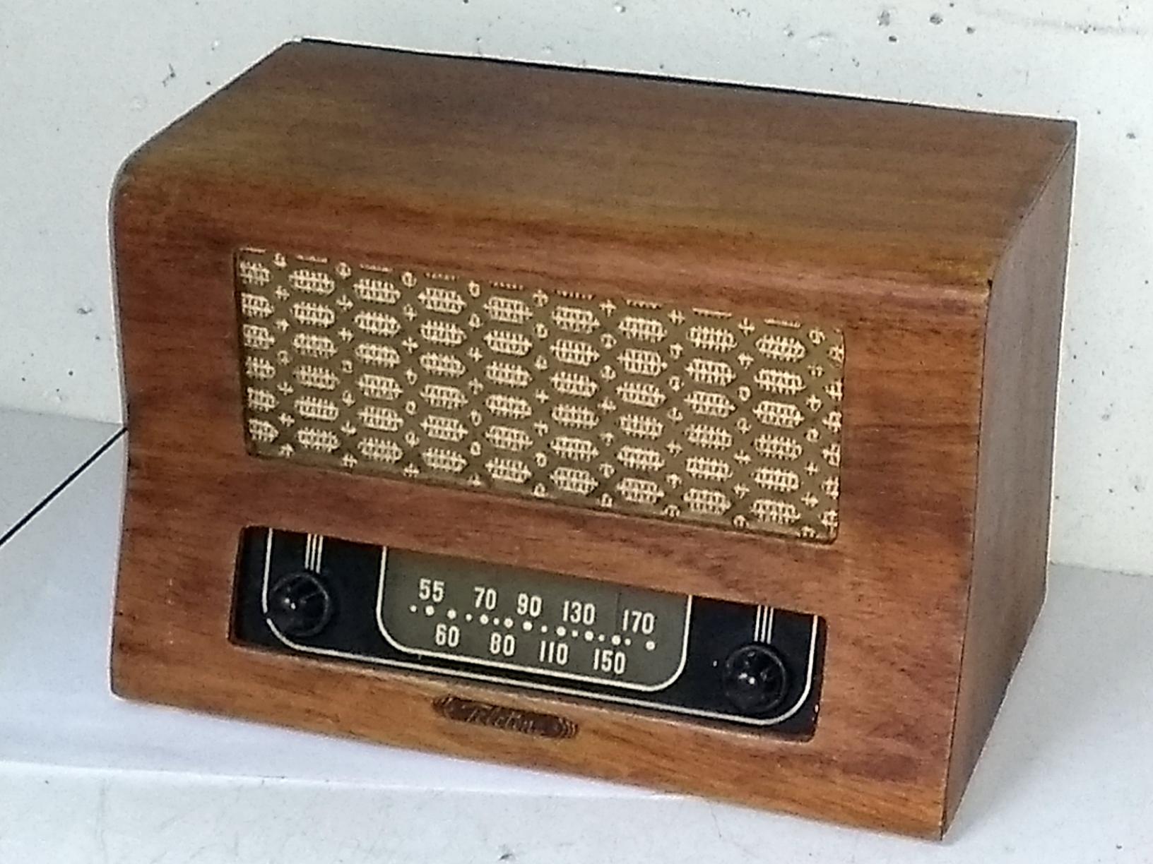 The Teletone 111 of 1948
came to me as a modified AA5 radio.
Originally made only for 110V operation,
resistors had been added to suit the radio to 220V.
Resistors that dissipate 16W can run very hot,
and these were placed directly under the wood cabinet.
I rewired this radio to the Sanshin model,
using two 1uF capacitors in parallel (2uF together),
reducing the power consumption from 38 to 23W.
The Teletone 111 of 1948
came to me as a modified AA5 radio.
Originally made only for 110V operation,
resistors had been added to suit the radio to 220V.
Resistors that dissipate 16W can run very hot,
and these were placed directly under the wood cabinet.
I rewired this radio to the Sanshin model,
using two 1uF capacitors in parallel (2uF together),
reducing the power consumption from 38 to 23W.
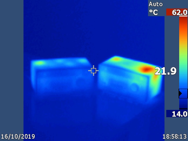
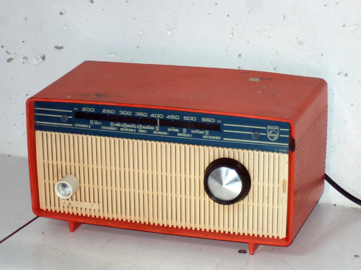 For some time I had two Philips B0X19U sets,
one in quite bad condition (heat damage around the output tube),
and I used it to experiment with different power supplies.
For some time I had two Philips B0X19U sets,
one in quite bad condition (heat damage around the output tube),
and I used it to experiment with different power supplies.
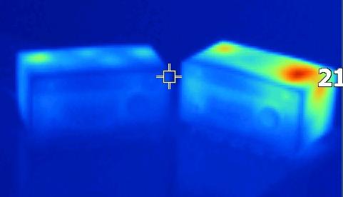 The Sanshin schema reduces power consumption from 43 to 17W
and here is a heat camera image of the two sets lined up together.
The Sanshin schema reduces power consumption from 43 to 17W
and here is a heat camera image of the two sets lined up together.
Just for the fun of trying out the Sanshin schema
for a 300mA heater chain,
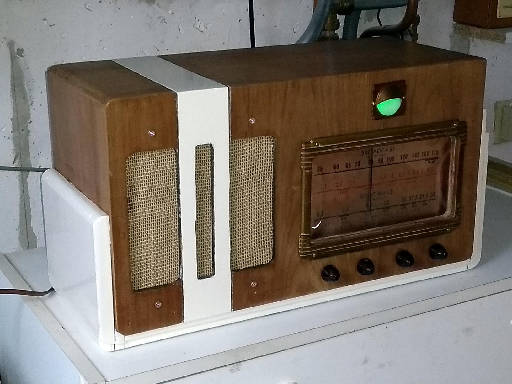 I bought a Weston radio
in quite bad condition.
Rectifier and tuning eye were missing,
and a lot of strange mods had been done.
To supply the chain with 300mA current,
we need 4.4uF of ballast,
which I made up of two 2.2uF in parallel.
The resistance of this heater chain is quite low,
which could lead to a very high B+ voltage.
So in series with the 1N4007 rectifier diode,
I placed a limiter RL of 1 kiloOhm.
With the smoothing resistor of 1k,
this resulted in 110V on C1 and 90V on C2.
I bought a Weston radio
in quite bad condition.
Rectifier and tuning eye were missing,
and a lot of strange mods had been done.
To supply the chain with 300mA current,
we need 4.4uF of ballast,
which I made up of two 2.2uF in parallel.
The resistance of this heater chain is quite low,
which could lead to a very high B+ voltage.
So in series with the 1N4007 rectifier diode,
I placed a limiter RL of 1 kiloOhm.
With the smoothing resistor of 1k,
this resulted in 110V on C1 and 90V on C2.