506
Item nr.
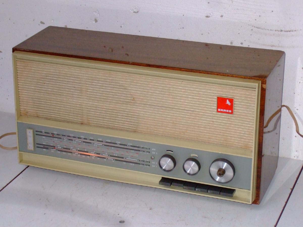
Hybrid tropical radio.
| Production | The Netherlands, 1965. |
|---|---|
| Bands | MW (182-577m), SW3 (62.4-183m), S2 (22.2-62.5m), SW1 (11.3-22.7). |
| Tubes | ECL86 (LF amplifier). |
| Semi- conductors | 2x 2SA234C (osc/mix, 1st IF), 2SA12D (2nd IF), 1N34A (det.), HR30 (rect.). |
| Cabinet | Wood. Size 42x21x16cm. |
| Power | AC 90/110/127/220/250V, 30W. |
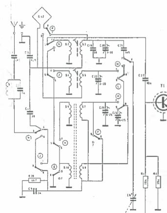
| Documents | Schema (thanks Jan H.), Slide deck. |
 That the set was made for use in the tropics can be deduced from (1) lack of FM, which was standard on European sets in 1965; (2) band plan including Tropic Band 1.6-4MHz; (3) voltage caroussel has 90V and 250V; (4) Made in Holland printed in Dutch, English, French, and Spanish.
  The radio is a hybrid, using transistors in the HF part and a single tube ECL86 as audio amplifier. The continental version RA653 has 6 transistors, three of which are used for FM exclusively, so it comes as no surprise that the RA6531 has three transistors. Supply of the transistors is derived from the B+ voltage for the tubes by means of a resistor voltage divider.
The continental RA653 has the FM, and Medium, Long and one Short Wave band, but most consumers would use it for national broadcasts, and use the Long, Medium, and FM mainly. To ease Short Wave tuning, the tropical version has a fine tune control; this is really handy for regular SW listening.
 You might have to rotate your set from time to time, because it is equipped ith adequate, but directional antennas. The ferrite rod for MW and Tropicl band is mounted parallel to the back panel, making the radio sensitive for stations in the front and back of the radio. For SW (1 and 2) there is a loop antenna mounted in the front panel, making the radio sensitive to stations to the left and right of the radio.
 Pulling the chassis can be a puzzle for Erres sets! For this radio: (1) Unscrew back (4 screws); (2) Unscrew (4 screws) and remove service panel on bottom; (3) Pull the four knobs; (4) Unsolder loudspeaker (brown wire above and black wire under); (5) Unsolder loop antenna (next to tuning cap); (6) Unscrew (3 different screw) and remove dial; (7) Through service panel, unhook dial pointer (photo); (8) Pull signal wheels from volume and tone pots (vilt rings in front of them); (9) Unscrew 3 bottom bolts of chassis; (10) Pull chassis.
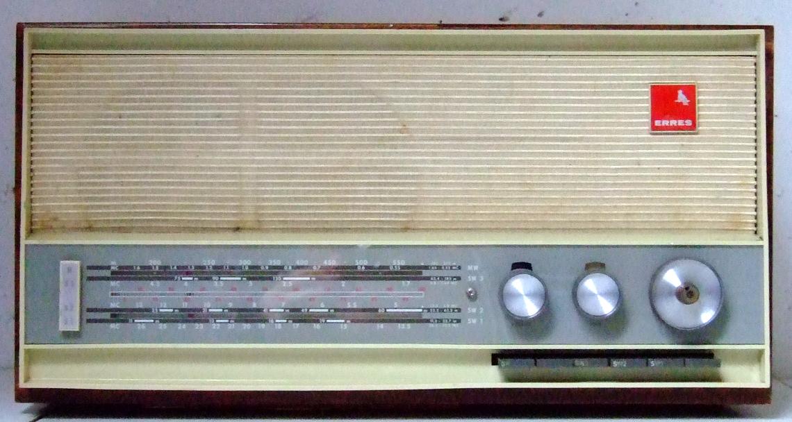 The NVHR schema database usually depicts sets straight from the front as in this picture right.
Behind the tuning knob, the dial is marked RA6531 UNIV and 50169870.
| Obtained | 12/2019 from Ruud; sn=3111. |
|---|---|
| Condition | 8; complete, works, some wood chips missing, fine tune knob is ugly. |
| Value (est.) | 22€. |
| Sound sample | PLAY SOUND Around 2019, my beloved station Radio Paradijs at 1584AM got replaced by Fidelio, with similar (Golden Oldies) programming. If you like hearing high notes in your music, an Erres tropical set is probably not your thing. |
The radio was a little dirty, but worked well, with the only problem being the band switch, of which the buttons would not lock well. 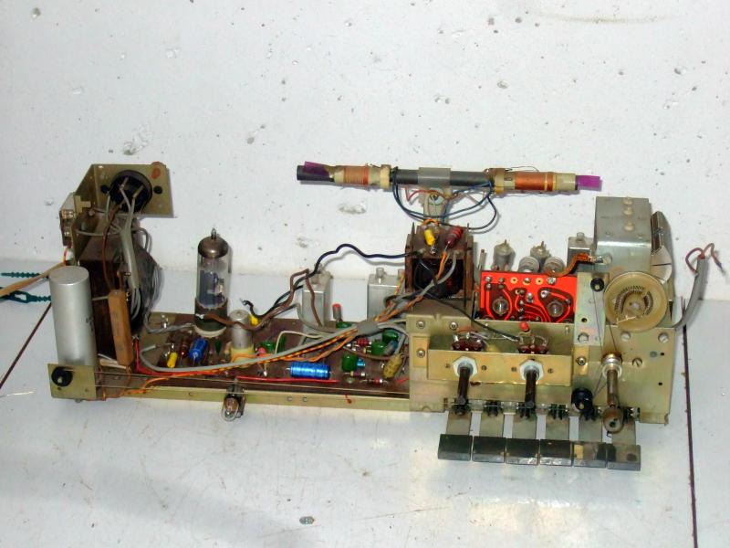 I replaced the standard capacitors (coupling, Boucherot, etc) and measured voltages,
  all being OK, and the power consumption being 30W, exactly according specs. The ECL86 tube is vulnerable for print carbonization: after 10 to 30 minutes, the grid voltage tends to go up and the kathode current as well. I set the voltage caroussel to 250V (push in the caroussel with your screw driver to do this), thus reducing the power consumption to 20W, and without compromising the sensitivity. The photo right shows the power transformer plus LF part; the high tension voltage does not get anywhere further to the right than the electrolyt on the board.
 The band switch is built in very tightly and difficult to reach. By inspecting the chassis carefully, I found out the location of the lever that locks the switching strips in position: it is in the front of the switch, just under the switching strips. I tilted the radio upside down and dripped some BreakFree in each of the strips, and after some "piano playing" the oil had spread sufficiently and the prolem was gone.
 The fine tuning knob is in the center of the tuning knob and it is a very handy feature indeed! Without it, precise tuning on the Short Wave bands is almost impossible. I'd say it would come handy in the Tropical Bands, too! Unfortunately, the knob misses a metal shielding, which I suppose was there originally.