388
Item nr.
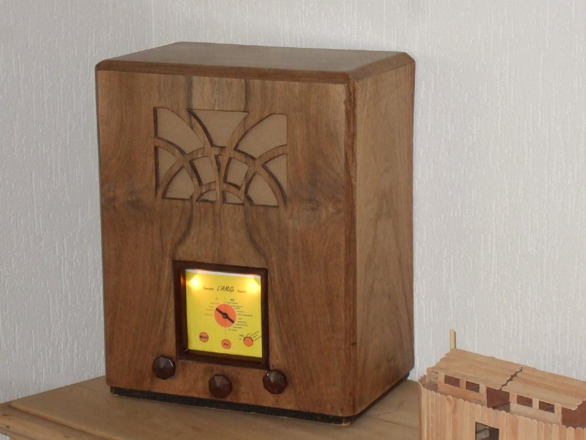
Long/Medium Wave is LoMeWa, or L'Amigo in Dutch
| Production | The Netherlands, 2015.
Price was 30€ (15 for cabinet, 7,50 for scrap chassis, some capacitors). |
|---|---|
| Bands | LW, MW (550-1600kHz), presets 675, 1008, 1584, 828kHz. |
| Tubes | ECC40 (pre-amp), EL41 (output). |
| Semi- conductors | MK484 (tuner IC), 1N4007 (6V rectifier), 2x 1N4007 (voltage reference), 2x 1N4007 (B+ rectifier). |
| Cabinet | Wood. Size 36x47x24cm. Weight 8.6kg. |
| Power | 230V. |
| Documents | Schema power supply, Tuner, AF amp, Dial. |
Because a lot of Dutch MW stations close down nowadays, I wanted my radio to receive LW as well as MW. I was quite succesful with a small MK484 matchbox project a few weeks before, so I decided that the tuner part would be MK484 based. The available tube sockets were Rimlock types, so I decided to go for an early fifties smell and have an AF amplifier with ECC40 and EL41. I wanted a cascade preamp, because the signal output of the MK484 is much less than that of a tubed tuner. I started out with a rough design, but during building and selecting parts, I deviated a little from my plan.
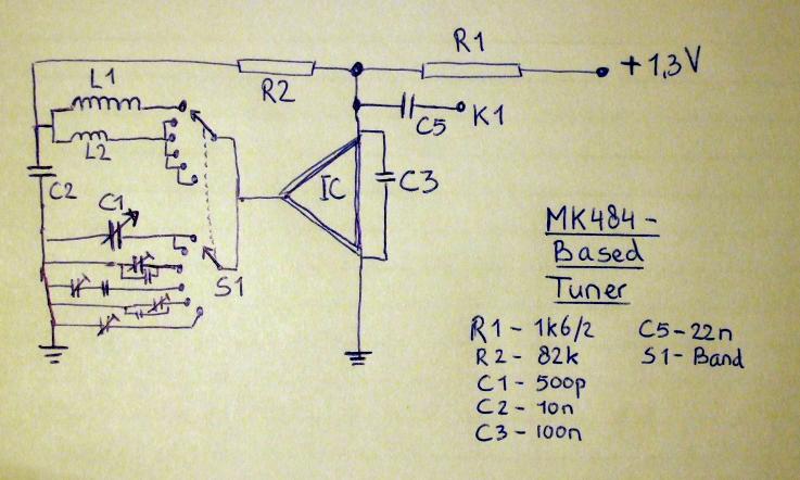 Data sheets of the MK484 are easy to find, but only have two pages with basically little more than the construction of the match box radio. Fortunately, it is as good as equal to the older ZN414 and its sheets can be used. Only be aware of the reversed pin layout!
  I wanted to switch between the MW and LW coil of my ferrite rod, but searching for switches I only found a multi deck six position switch. And the old chassis had a few trimmers still on it, so I got the idea to use four positions for presets, using a second deck of the switch between capacitors. One trimmer roughly gave the frequency of 747kHz. For 675 (position 3) I added a 22p cap. For 1008 (position 4) I put 560p in series. 1584 (position 5) has a different trimmer. For 828 (pos 6) I just use one of the trimmers.
The example schema's for MK484 all connect the tuning cap to the top of the agc buffer C2. But I found out that my tuning cap is connected to the chassis by construction, to I grounded the cold side of all tuning capacity. This makes C2 (22nF) part of the tuning circuit, but this hardly makes any difference.
 The ECC40 is a cascade preamp, and the EL41 is the output tube. Because the output of the MK484 is far too small to overdrive a triode, I placed the volume control just before the second amplifying stage, so listening at low volume reduces the noise of the first stage. The volume control is directly connected to a jack at the back, for connecting an MP3 player. The low output impedance of the player will completely shortcut the signal from the first stage, so connecting the player immediately silences the radio.
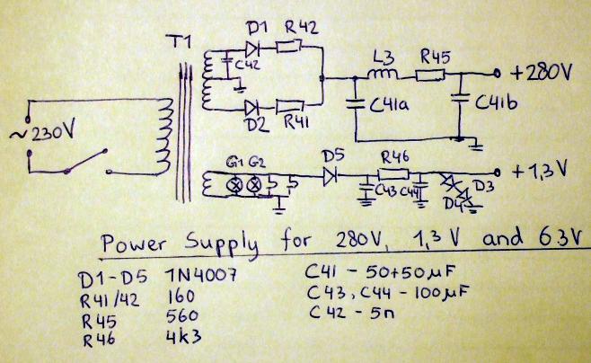
 The supply for the tubes has double phase rectification with 1N4007's and smoothing through filter caps and a choke. The 1.4V supply for the tuner has one sided rectification, smoothing and two 1N4007's form a voltage reference. This works very well, the voltage is very stable at about 1.38V. The 6.3V coil of T1 also supplies the light bulbs and tube heaters.
| Obtained | 3/2015 from Scrap parts. |
|---|---|
| Condition | 8. |
| Value (est.) | 15€. |
| Sound sample | PLAY SOUND If you tune the MW dial to station, the preset switch allows you to hear five stations in a row without touching the dial. You hear (1) Deutschlandfunk commenting on the loss of the Germanwing plane on March 24, 2015, (2) Radio Maria sing O God, You are my God, I seek you, (3) Groot Nieuws radio announce the 20 hours news, (4) Radio Paradise play a popsong, (5) NPO5 explain that Minister Kamp thinks it is cheaper to use three wind parks. Germany and Paradise come in quite weak and the reception of those stations isn't very clear. |
 The chassis and cabinet come from a Tonalux 706 radio from 1937. The tube sockets and transformers come from a Philips BX520A chassis from 1952. Mid February 2015 I started to save the necessary parts from the scrap radios, and clean the chassis and soldering lips.

 Later in February I soldered all the components on the chassis. The power supply was completed on February 24, 2015. The amplifier was completed on February 27 and tested with an MP3 player.Then I wired the tuner and got my first stations received on February 27. The next days were used to test some improvements to sound and reception. Then I attached some paper behind the dial pointer and marked the position of stations I received.

 I designed the dial with Powerpoint on March 15, printed it and Wout helped me to laminate it. The knobs had rusted screws stuck in them and Bert helped me out by drilling them clean. On March 18 I could place the dial and knobs on the chassis.
On March 22, I glued the speaker cloth in the radio and assembled the set and started the testing period.
During the first weeks of tests I found a few things should be improved. (1) Blue cloth is too dark, I should put light brown; set is more in one tone now. (2) The sound is too shrill, I must put a 4nF capacitor across the volume control. (3) The dial is too pink, I will print it more yellowish; it came out very yellow. (4) The edge of the dial flips under the edge of the dial hole, it must be cut 1cm higher. (5) Tighten the right dial light. (6) Saw the axis of the volume pot 8mm shorter. (7) Retune Ottozender, preset 6 and the dial marking to 828kHz (to anticipate cease of Nostalgia). (8) Remove annoying crackling noise (this was due to bad EL41).