445
Item nr.
Funny radio with interesting circuits
| Production | Japan, 1964. |
|---|---|
| Bands | MW (540-1605kHz), MB (1,6-4,8MHz), SW1 (4,8-14,5MHz), SW2 (10,5-30MHz), VHF (142-148MHz); IF is 452kHz. |
| Tubes | ECC85/6AQ8 (VHF amp), EF94/6AU6 (VHF mixer), ECC85/6AQ8 (VHF osc), EF93/6BA6 (RF amp), EK90/6BE6 (mixer), ECC85/6AQ8 (osc), EF93/6BA6 (1st IF amp), EF93/6BA6 (2nd IF amp), EAA91/6AL5 (det, ANL), EK90/6BE6 (prod.det.), ECC85/6AQ8 (AF amp, BFO), EL90/6AQ5 (output), ECC85/6AQ8 (Q-mult., Marker), EZ81/6CA4 (Rect.), OA2 (Volt.regulator). |
| Semi- conductors | 1N60. |
| Cabinet | Steel. Size 43x19x26cm. Weight 10.7kg. |
| Power | AC 220V@65W. |
| Documents | Schema. |
RF Front end: While in most consumer sets, the RF Front end (the part before the IF amplification) contains only a single tube, this Jennen has a front end with three tubes. Broadcast sets usually have a converter tube here, containing an oscillator and amplifying mixer in one enveloppe, such as the ECH81. This radio has an extra tube for the RF amplification, and further, the oscillator and mixer are separate tubes.
Fine tuning: The main tuning is a three gang variable capacitor, and the fine tuning is an extra three gang VC of smaller capacity. So, unlike some shortwave sets, the fine tuning actually tunes all varying circuits and allows the circuits to remain fully synchronised. The fine tuning mechanism also has a mechanical tuning indication: the lower part of the dial has spread bands for the ham frequencies, accurate when the main dial is set precisely to certain indicated points. These are multiples of 100kHz, so they can be tuned exactly with help of the marker oscillator. This should allow mechanical tuning to about 1 to 2kHz precision. 
2m Converter: A three tube unit that downconverts frequencies in the 140MHz range by 137MHz and feeds it to the antenna jack. Selecting the converter also selects band SW1. The oscillator is crystal-controlled, with a crystal of 45.666MHz. The same crystal allows downconversion by 45.666MHz, for a 6m front end. In the European versions, mixing is with the third harmonic to get at the 2m band.
IF stage: There are two IF amplification tubes, which also implies that there are three IF transformers. For this radio, one can use the manual for the similar Lafayette HE-80, but that set lists an IF of 455kHz. That value was problematic in The Netherlands because of interference with some strong coastal stations. So, this set was retuned to have an IF of 452kHz.
Q-Multiplier: A narrow banded amplifier (nearly an oscillator) allows to selectively boost a frequency near the IF center frequency. Gain can be controlled (even beyond oscillation) and so can frequency. So a very narrow band can be selected out of the IF band pass. Selectivity is specified as a 65dB fall at 10kc, but with the Q-multiplier this increases to 95dB.
Detectors: There is a product detector for SSB (and CW), to be used together with the BFO, and an FM detector that can operate for 27mc communications and on the 2m band.
Marker oscillator: 
 A crystal oscillator with many harmonics can be switched to the antenna input, allowing exact tuning to multiples of 100kHz. My set missed the crystal, and on many photo's on the internet I saw no crystal. It isn't even depicted on the photo in the service manual. So I think that this crystal was optional, perhaps they were very expensive?? I tried to fit in a 6x2mm microcrystal but got no succes with it. Kobus sent me a crystal (left) and then the marker oscillator (right) worked OK.
Finally, there is an S-meter and jacks for connecting a recorder or a headset.
| Obtained | 7/2016 from Tony Ouwehand. |
|---|---|
| Condition | 8; calibration osc. and 2m unit currently not working.. |
| Disposed | Sold 5/2020. |
 it looked a little bit poor, but not desparate. It was like, sort of, working and complete (although the knobs are not original). The worst was the situation of the glass dial (lettering worn out). I checked tubes and voltages and found everything to be OK except the current through the output tube. Replacing the coupling cap C49 was the only electrical repair necessary.
  You are supposed to use the radio with an external speaker, but I don't really like this. So I strapped a small speaker to the IF cans with tierips and connected it to the external jack. This isn't really a modification of the radio. Behind the speaker you see my first attempt of replacing the missing 100kHz crystal for the marker oscillator.

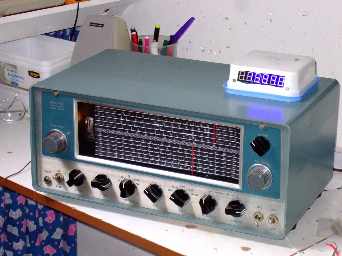
 Following an experiment with a junk chassis, I constructed a digital frequency display for the Jennen. This unit is just a digital frequency counter with a DC supply, connected to the oscillator through 22p. But I didn't want to make irreversible mods or damage this beautiful set, so I decided to place the unit on top of the radio in a fully removable way. The three connections are soldered but can easily be removed again, and halfway there are screw connectors for easy pulling of the chassis. Using a tube radio with digital frequency readout is a fantastic experience, by the way.