446
Item nr.
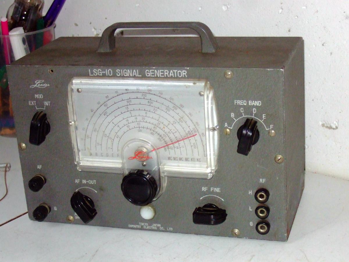
Small service instrument
| Production | Japan, 1960. |
|---|---|
| Bands | 120kHz - 260MHz in 6 bands. |
| Tubes | 6AR5 (LF osc or amp), 12BH7 (RF osc and buffer). |
| Semi- conductors | diode rectifier. |
| Cabinet | Steel. Size 25x16x12cm. Weight 2.3kg. |
| Power | 230V (11W). |
| Documents | site. |
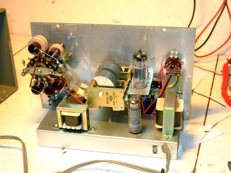
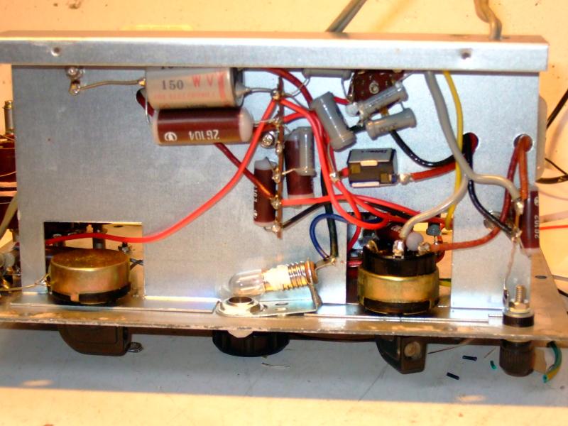 Such an instrument need not be terribly complicated and it contains just two tubes and a handful of other components, as you can see from these two inside pictures.
| Obtained | 9/2016 from NVHR Market. |
|---|---|
| Condition | 8. |
| Value (est.) | 15€. |
| Sound sample | PLAY SOUND Zero beat to a station to read out the frequency. |
AF input and output and RF output is by banana plugs so it is easy to produce all kinds of leads. The RF signal can be modulated from an external source, but as tube sets have high impedances, it needs quite some voltage to get enough modulation. With an MP3 player connected, you'll hardly hear the sound in your radio.
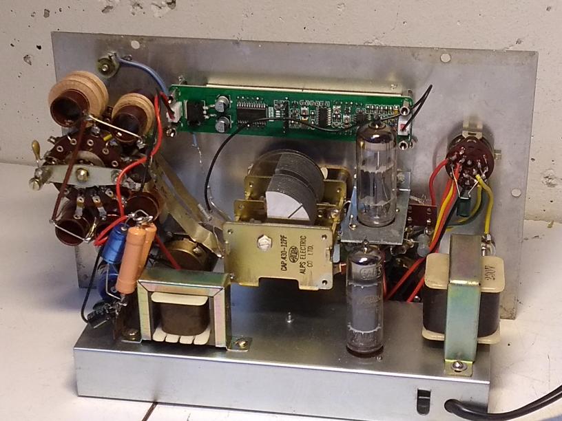
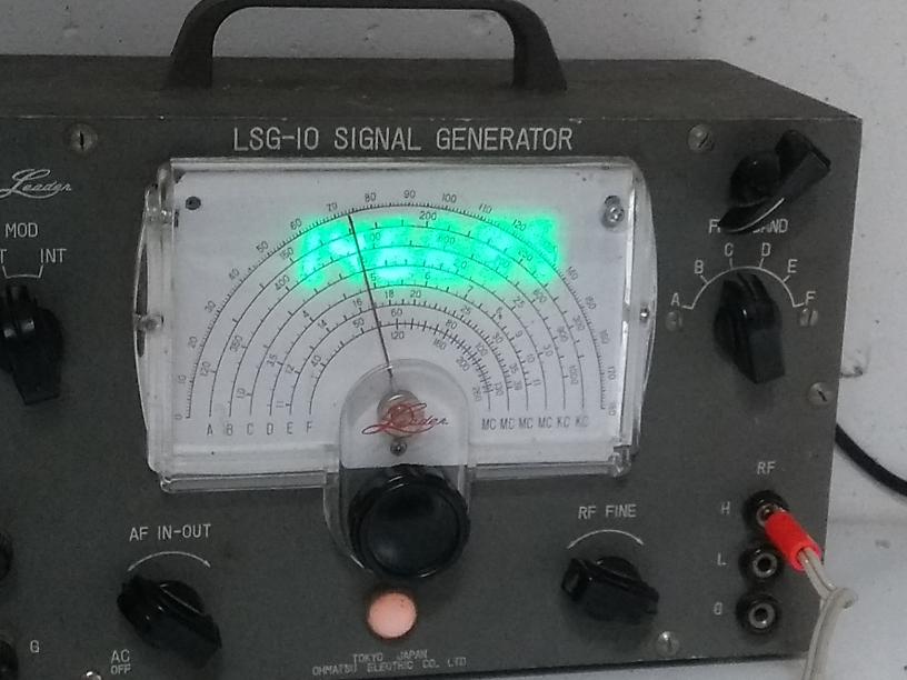 Two modifications allow me to work more precisely with this LSG-10 than is possible with most. I installed a digital frequency readout, an eight digit Cymometer that measures with a resolution of 10Hz. This is a great improvement over the standard precision of one to several kiloHertz. (The Cymometer allows measurement with 1Hz precision, but the 1sec refresh time makes it unpleasant to use.) The display is invisible from the outside when the set is switched off, because it is placed behind the paper dial. Only when switched on, the digits light up and shine through the dial. They are a little bit hard to read and very hard to photograph. To also control the frequency more precisely, I added a small trimming capacitance to the tuning tank. The smal capacitor allows to "zero beat" Radio Paradise, after which the frequency can be read from the display.
For some years, the unit suffered some hum (both in frequency and amplitude of the signal). This was caused by the filter capacitors, which were replaced in May 2024.