519
Item nr.
World receiver for expats.
| Production | Benelux, 1955.
Price was fl 328. |
|---|---|
| Bands | MW (185-580m), TB (60-187m), 4xSW (32.7-60m, 23-32.9m, 17-25.8m, 10.9-17m); IF 452kHz. |
| Tubes | UF41 (pre), UCH42 (mix), UBF80 (IF, det, AGC), UAF42 (AF), UL41 (output), UY41 (rect), UM4 (tuning), 2x8097D-00 (dial lights). |
| Cabinet | Bakelite. Size 55x38x23cm. |
| Power | ACDC, 110/125/200/220V, 50W. |
| Documents | Service docs, slide deck. |
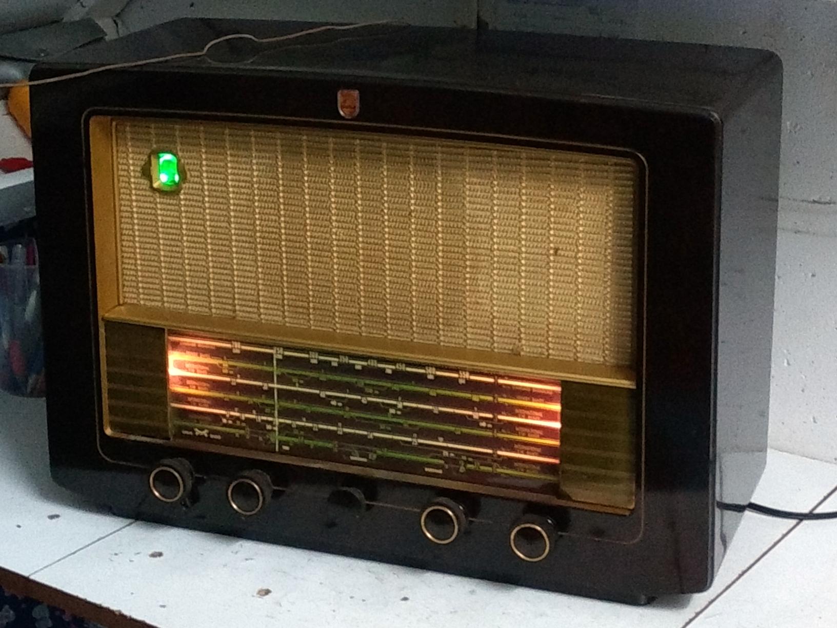
Most AC/DC sets are quite cheap, small units, because a popular reason for the transformerless design was reduction in size and cost. But this AC/DC set is quite luxereous, has an AC companion (the BX645A), so it was clearly made for the possibility of DC operation. Intended for tropical countries (indicated by the 5 as third digit in the type number), it has no Long Wave, but covers the Tropical Bands, completely from 180 to 60 meters.
My cabinet looks like very shiny bakelite, but the advertisement suggests there should be wood printing om the front. Since it was new, the radio was in possession of just one family, I bought it from the grandson of the lady who bought it in the fifties. This lady was no longer alive, and the descendants were not aware of their mother having an emigration background.
| Obtained | 7/2020 from Boyd via Marktplaats; sn=A58511. |
|---|---|
| Condition | 8. |
| Value (est.) | 33€. |
| Sound sample | PLAY SOUND The sound can be very bassy when the tone switch is set to full bass. |
 When I picked up the radio, I was told it worked and this was actually the case when I tried it (playing through a light bulb). Fortunately, I had hooked it through a Watt-meter and after a few minutes saw the power draw rise from 50 to 70 and 80 Watts. Time to switch off! During the brief test I had observed that one dial light was dead, and tuning slipped.
  When removing the knobs, I observed that they had the original wax protection, so the chassis probably was never pulled before. Inside, of course I found a lot of dust, and all original parts from 1956. Tubes measured fine. I replaced the paper capacitors and the output tube cathode capacitor. Pay special attention to the capacitors connecting the circuitry to touchable parts (C63, C28, C9, C11); because the chassis is connected to the mains, these should ideally be safety capacitors. Greasing the tuning cap and various guide wheels restored the operation of the tuning knob.
The original dial lights are type 8097D, rated 19V at 97mA. Because the mains voltage is higher nowadays (230V instead of 220V), I placed bulbs rated 24V at 97mA so the extra voltage goes into the lights. This isn't really necessary (the higher voltage falls within the radio's tolerance), but I don't want the heaters to run too hot, as this increases the power consumption, and hence heat, in the radio.
 The fine tuning consists of little coils, S29 for bands 4/5/6 and S30 for band 3, in the oscillator circuit. Their cores are nail-shaped pins, that run in and out by the fine tuning knob. I found the pressure wheels detoriated and displaced. I pushed them back as good as possible, and fixated them with hot glue.
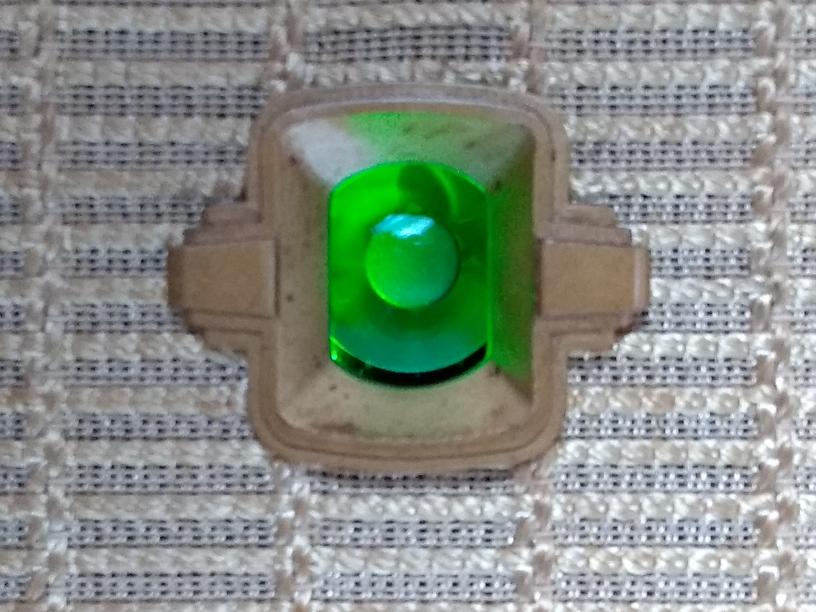
 Tuning eyes are generally worn out and lightless after sixty years or more. I faked the effect by installing four green LEDs around the eye, fed from the plate current of B3 (UBF80). Because the AGC operation influences the plate current, the LEDs react by dimming when tuning is more precise. So this creates a reversed visual effect.
 I temporarily removed one knob to demonstrate what the radio should absolutely not look like. The chassis of Universal sets is connected to the mains, so touching an axis behind a missing knob may be lethal! Never play these sets with missing knobs and never replace them by metal knobs!