70
Item nr.
Dropping resistor replaced by cap.
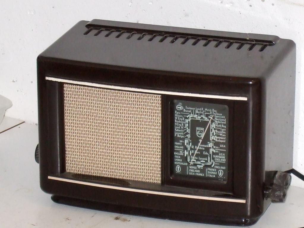
| Production | The Netherlands, 1944.
Price was 135 guilders. |
|---|---|
| Bands | LW, MW, SW. |
| Tubes | UCH21, UCH21, UBL21, UY1N. |
| Cabinet | Bakelite. Size 25x16x14cm. Weight 2.75 kg. |
| Power | ACDC 110/220V. |
| Documents | Service Doc. |
| Obtained | 7/1997 from Kofferbakmarkt Camperduin, sn=E22254. |
|---|---|
| Condition | 7. |
| Disposed | Sold 4/2016. |
| Sound sample | PLAY SOUND This is the message that the radio was built to play. Prime Minister Gerbrandy announces the capitulation of the Germans and the liberation of The Netherlands. |
 I could clean and polish the cabinet and find some suitable cloth for the grille. Then I had to dig out most of the capacitors and resistors under the chassis in order to reach at the volume pot and switch. I wanted to replace most of these, anyways. Altogether I removed about 65 capacitors, resistors, and wire pieces with crumbled insulation. Only the circuitry around the mixer stage remained in place, because there were no paper capacitors, nor crumbled insulation in that part.
To reduce the heat developed in the small bakelite cabinet, I modified the power supply of the set. The rectifier (UY1N) was replaced by a silicon diode, and the series filaments were fed through a capacitor instead of a series resistor. This avoids some 14W of power to be generated in the hot corner of the radio. Another advantage is that a 100mA pilot lamp can be included in the 100mA heater string. With resistor-fed heater strings this is impossible because the lamp would die instantly of the startup current (through the cold heaters). Power consumption of my radio is now 28W at 230V supply (measured in December 2013).
 Here is a picture of the chassis, where the blue tower on the right is a pack of seven 220nF capacitors at the location of the former UY1N rectifier.
I collected replacement parts from the electronics supplier and started to reassemble the set. Meanwhile I found one of the two missing knobs for the set in the inheritance of Mr. Krijnen. Because the original switching potmeter could not be repaired, a more modern substitute was used. After soldering everything in place I checked the main circuitry with an ohmmeter and applied power, but nothing! As it turned out, I had forgotten to ground the appropriate side of the volume potmeter, and when I had made good for this omission I was rewarded for many evenings of work with the sound of Dutch radio stations coming from the speaker.
The sensitivity is below par, however. Normally one would try to align the set, but this radio is fitted with unalignable (fixed) IF transformers and their quality, even after 50 years, simply has to be taken for granted. The tubes tested good and I decided to increase B+ (from 105V to 125V for the HF tubes) to get a little more gain out of the tubes. The current state of the radio is satisfactory, despite several sacrifices to the originality. It receives MW and LW reasonnably well, but SW is silent (no oscillation in the mixer there).
In the Fall of 2013 a second 208U found its way to my repair table; I repaired that set for Tanneke.