289
Item nr.
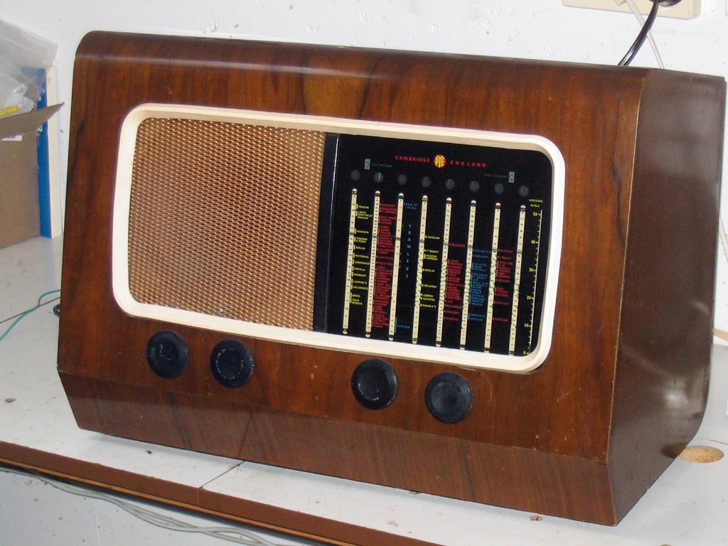
Brittish shortwave set.
| Production | England (Cambridge), 1949.
Price was 334 guilders (in The Netherlands). |
|---|---|
| Bands | LW (1000-2000m), MW (190-560m), TB (1.5-4.0 Mc/s), 49m (5.9-6.3 Mc/s), 31m (9.2-9.9 Mc/s), 25m (11.4-12.2 Mc/s), 19m (14.8-15.7 Mc/s), 16m (17.2-18.3 Mc/s), Logging Scale 0-50. |
| Tubes | ECH35 (mixer), EF39 (Int.Freq.), EBC33 (Det. And AF amp), EL33 (output), AZ31 (rectifier). |
| Cabinet |  Wood with Pye logo on top .
Size 50x35x26 cm. Wood with Pye logo on top .
Size 50x35x26 cm.
|
| Power | AC 200-250V. |
| Documents | Schema. |
| Speaker |  20 cm, 8 Ohm Celestion. 20 cm, 8 Ohm Celestion. |
 The model was on sale in The Netherlands, but I got it with an English-style plug with a fuse and rectangular prones. So I guess it never played on Dutch soil. It isn't shaped with a flat top, but the entire radio including top is a bit tilted backward. This shape helped it escape the faith of many old radios: being used as a plant stand for several years, leading to nasty stains in the top. This radio came in an almost intact cabinet.
 Let us begin with the bandswitch, S1. Although the radio is a classical four stage superhet (without radiofrequent stage, or double conversion), there is a funny extra built in for the short wave ranges: the tuning capacitor has four sections. Two big ones (487pF each) are for the three lowest bands (Long, Medium, and Trawler), and two smaller ones (10 and 45pF) are for the five shortwave bands. So, the band switch, with eight positions for the eight bands, has six decks. Deck 1a switches the tuning capacitor in the antenna circuit and decks 1b and 1c switch the antenna coils. Then decks 1d and 1e switch the oscillator coils, and deck 1f switches the tuning capacitor for the oscillator section. Finally, deck 1g puts an extra 100pF fixed capacitor in parallel to the oscillator coils.
 The power of the radio is not switched with the volume control; so this is just a plain logarithmic 1Meg pot without switch. The radio has a combined switch for power, tone, and radio/PU, with seven positions. Decks 2a and 2b do what you expect from a tone switch: it places capacitors and resistors in the feedback circuit. Deck 2c disconnects the screen voltage of the HF tubes in PU mode, 2d switches the volume pot from the detector to the PU entry, and deck 2e is the (single lead) power switch.
There are four tone positions for radio: FIDelity, BRIght, MELody, SW; the latter position is nice for speech, with a quite flat sound without too many basses and trebles. The Pickup must do with two positions: FIDelity and MELody. Fidelity has high ranging trebles, while Melody emphasizes the basses more.
 Tuning on shortwave is a real pleasure. Observe that the bands together do not cover the entire 16-50m range of shortwaves (as is the case on, e.g., the Philips BX480A). The length of the shortwave bands is just a couple of hundred kiloHertz, the longest being the 19m and 16m band, both covering 900kHz. Compare this to the Medium Wave band, which is almost 1100kHz long, and you realise that tuning shortwave stations is almost as smooth as tuning a medium wave station. This radio has station names printed on the shortwave dials, just as is usual for medium and long wave dials.
I didn't get the knobs as nice as I wanted them. Each knob is engraved with text indicating its function, and the letters were filled with paint. But the knobs have worn out, causing the lettering to be nearly invisible. What it needs is, that somebody re-engraves the lettering in the knobs (but I can't do that myself now).
| Obtained | 12/2006 from NVHR Swap meet, SN=0723729. |
|---|---|
| Condition | 8. |
| Disposed | Sold 5/2009. |
| Sound sample | PLAY SOUND When this radio was built, no human foot had touched Chomolungma, or Mount Everest, and no human food was found on its pristine slopes. |
 The radio was very cheaply on sale at the NVHR Swap Meet in Driebergen. I was surprised that this radio, with cabinet and dial in good condition, could remain unsold there for more than 15 minutes. I took it home by bike.
 When I opened the radio, I found it to be one of the dustiest radios I had seen (left). The layer of dust was so thick and compact, that one could pick it up and lift the layer like a blanket. The loudspeaker cone was as good as stuffed with dust (right). Fortunately, our vacuum cleaner is always very hungry.

 I replaced the usual capacitors and switched on; there was a purple shine in the output tube, and plate voltage was way too high at 330V. The tube tester revealed that the output tube EL33 was emissionless; understandibly the plate voltage becomes too high when no current is taken, and understandibly the tube starts sparking with such a high voltage. Now an EL33 is not found on every street corner, and in none of the corners of my tube box. I took a good EL41 tube (an output tube of about the same time as the radio) and soldered it in an Octal base, and voila, a new EL33 was born. It even scored over 100% in the tube tester, and placing it in the radio made it come to life immediately.
 For the rest there was hardly anything wrong with the radio.
  Scratching of the volume pot was cured by cleaning the inside; there was DC on the volume pot, so I replaced C35. (Some critical caps, including the coupling cap to the output tube, were already replaced before I switched the radio on). The dial lights were dead, and replaced by fresh 6V bicycle lights. Now the radio inside is as on the right. Observe the EL33 being replaced by an EL41. Later Ite sent me a fresh EL33, which did not make much different for the sound, but rendered the radio more original (left).