523
Item nr.
Early AA5 with 300mA heaters.
| Production | USA, 1938. |
|---|---|
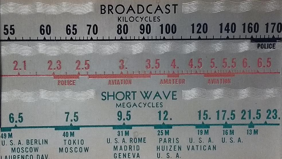
| Bands | MW (550-1700kc), TB (2.1-6.5Mc), SW (6.5-23Mc). |
| Tubes | 6K8 (osc./mix), 6D6 (MF), 6Q7 (det/AF), 25L6 (output), missing rectifier, missing tuning eye, 2 dial lamps. |
| Semi- conductors | 1N4007 (rect.), 2x Green LED (tuning). |
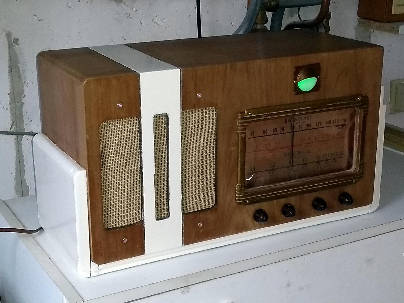
| Cabinet | Wood. Size 48x26x20cm. |
| Power | AC 230V @ 27W (Orig: ACDC 110/127V). |
 My radio has an extra knob (tone control), an extra tube (tuning eye), and an extra band (Tropical Band). But still the similarities make me believe that my radio also dates from around 1938. This is confirmed by the release years of the tubes.
| Obtained | 9/2020 from NFOR. |
|---|---|
| Condition | 6; plays but isolation dangerous. |
| Disposed | Sold 6/2021. |
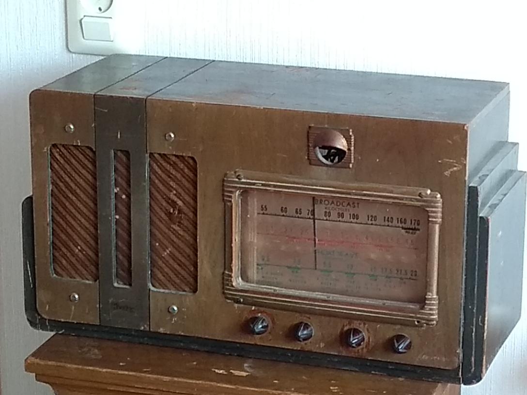 The radio came to me in a pretty deplorable condition, both cosmetically and electrically.
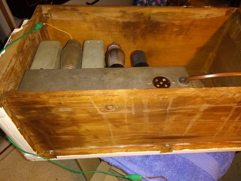
 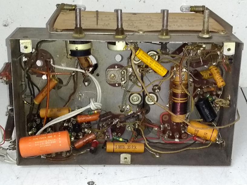 In the radio I found a lot of non-original parts and it was hard to guess what precisely was the function of it and how well this all performed. There were some strange ballast resistors besides the chassis (left on photo). I found out that the rectifier was replaced by a UY1N (100mA heater) and its heater was shunted by resistors to bypass 200mA of the current. So, these high power resistors probably had not been there originally. The radio has a socket for a resistive ballast tube, that could be changed to fit 110V or 120V mains. The socket of the ballast and of the rectifier showed significant burning damage (carbonization) from the heat generated.
 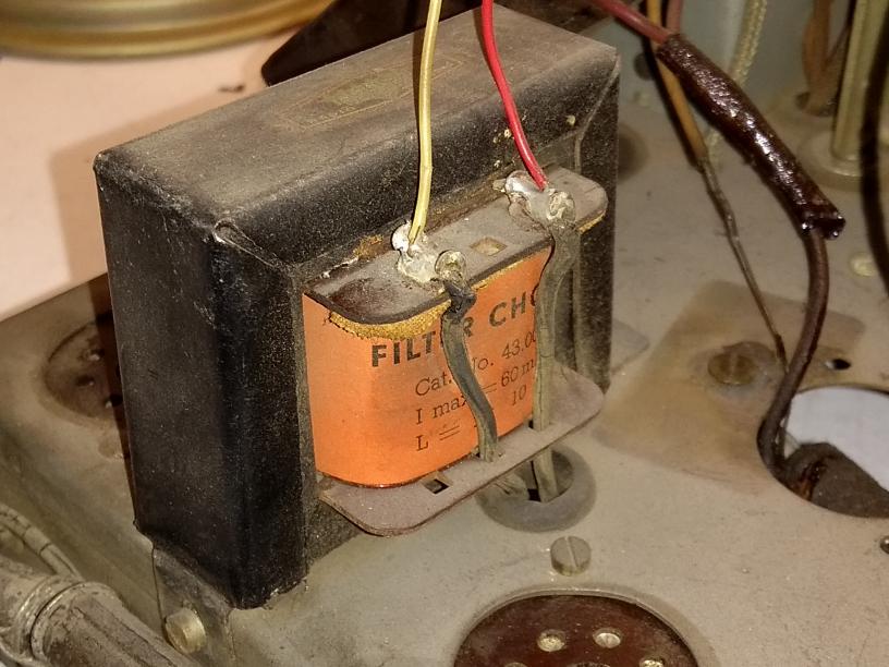 The output transformer was probably originally mounted on the speaker, but this was all gone and the speaker, clearly not the original one, was soldered to a choke coil connected to B+. I have the strongest possible doubt that this could ever have worked. I removed the choke and all unnecessary power supply additions, and rewired the heater supply to use a capacitive ballast following the Sanshin model. The ballast capacitor is 4.4uF (two of 2.2 parallel), shunted by a 94kOhm bleeder. The rectifier is a 1N4007 diode with 1k limitier in series, and I have 1k between the two filter caps. This gives 110V on the first capacitor and 91V on the second, about the same as the tubes had eighty years back in the USA. I placed a small output transformer on the chassis in lieu of the choke (had to drill one hole).
 So, with all the careful operation and thinking, this took me about three evenings of soldering and collecting parts. Upon powering up (at first with a series light bulb of course), the radio worked immediately. It isn't very sensitive; I receive dozens of stations in the evening with my longwire aerial, but without the longwire I receive nothing. With the Ruysdael mini transmitter I receive music on various frequencies all over the Broadcast, Tropical, and Shortwave band. Instead of the missing eye tube I mounted green LEDs, connected in the plate circuit of the IF tube.
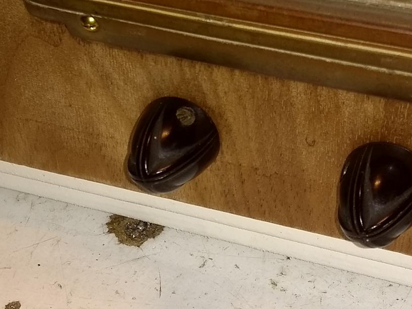
 In this radio, the knob screws are so close under the knob surface, that contact with the chassis is unavoidable when operating the radio. The chassis is connected to the mains, and the power switch is single deck, so this is also true when the radio is switched off. There is no back panel (presumably it was there 80 years ago), and "hot" chassis bolts extend under the chassis. Concluding, the result of my repair actions is a radio that is too dangerous to use, taking it into use would mean setting a booby trap in the house.